How technologies such as X-ray allow the testing of components without the need to break them in the process and why this is especially important in aerospace
Luke Robins & Arash Arsanjani, Ph.D. Fellow/ Early-Stage Researcher (TESLA project H2020-MSCA-ITN) at the Institute of Microwave and Photonic Engineering (IHF), Graz University of Technology
What is Non-destructive testing?
Non-destructive testing (NDT) is a collection of inspection methods that can evaluate components without the need to physically alter or damage them. This is especially useful in cases where the component needs to be maintained in an operational or sealed state but requires analysis or fault detection. Examples of common NDT testing methods include Radiography, Ultrasonic, Magnetic particle inspection, leak and liquid penetrant testing. All of these can be used to extract different information from the device under test without alterations. A basic example of leak testing could be filling a bottle or fluid container with water and seeing if there are any leaks; this provides useful information on the object’s functionality without the need to change or damage it in the process.
X-Ray as an example?
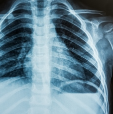
Figure 1: Chest X-ray (https://medlineplus.gov/xrays.html)
A common testing method falling under radiography is X-ray. This testing is very widely known from the medical field, where X-rays are used to create images of the bones inside the body, for example. This allows a doctor to see if there are broken bones or obstructions without making an incision and inspect. This is safer, cheaper, quicker and less painful for the patient, and in some cases would be impossible to see otherwise.
How does X-ray work
A simple way to
understand how X-ray imaging works is to imagine a torch that shines a light
beam onto a dark background. If you hold different shapes cut out of paper in
front of the torch, you will see these projected as a dark representation of
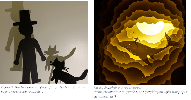
itself on the background. This example can be seen demonstrated with the shadow
puppets in Figure 2. If a thin paper or a strong light is used, some more of
the light will pass through it, and the shadow in the wall will be lighter
similar to the example in Figure 3. This shows Contrasts in the image based on
how easily the light passes through obstacles. For the medical X-ray example in
Figure 1, the principle is similar. The X-rays also travel from a source
(torch) through the object to a collector(wall), creating the image. The areas
where the X-rays travel through the most are the darkest, and the areas like
bones that do not let most of the rays pass through are the whitest. X-rays
travel differently through different materials; the type of material and energy
of the X-rays can influence how dark or light areas of the image are exposed.
X-ray for aerospace
Satellites enable numerous technologies, which are often taken for granted and expected to just work e.g., technologies such as GPS, satellite television or weather forecasting. This expected reliability comes at the price of rigorous pre-flight testing and certification. Launching objects into space is hugely expensive, dangerous and can put people/systems or other technologies at risk if a failure occurs. Each system undergoes multiple testing and verification stages before a component is finalised. Once the actual part to be flown is manufactured, it needs to be tested before launch. This component still needs to be fully functional for further use, therefore the processes used for testing must be non-destructive. As an example, you can see below some computed tomography images of an aircraft nozzle, injectors, and valve bodies. These images provide the chance of validating highly critical items before being approved for the space flight without damaging or altering them.
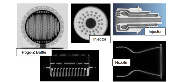
Figure 4: Aerospace Example X-rays(Source: https://www.researchgate.net/publication/273741390_Summary_of_NDE_of_additive_manufacturing_efforts_in_NASA)
X-ray use in the TESLA project
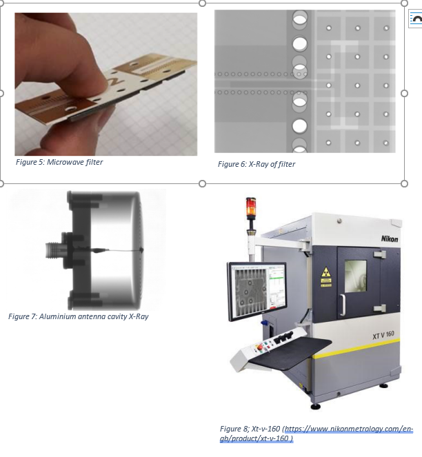
The work being conducted in the TESLA-project, as well as at TU Graz, aims to be used in the next generation of space telecommunication systems. These systems will have much higher speed and have higher data rate requirements than the current state of the art. The requirements drive the size of these components to be smaller and smaller (due to the wavelengths used), meaning the fabrication process should be even more accurate and precise than before. The nature of the components being made is also often such that they are sealed for their operation. X-ray provides a practical way to analyse the inside of these sealed components without needing to disassemble, damage or make them non-functional. Such a sealed component (a microwave filter) can be seen in Figure 5. This component consists of multiple layers, all of which need to be precisely aligned for correct operation. Figure 6 is an X-ray image of the inside of the component, which was used to determine that a large misalignment is present, which is one of the root causes of the device’s degraded performance. The image shown in Figure 6 is lighter for the areas where more X-rays pass through and darker for the less penetrable areas. This information can then be used in the next design iterations to improve the fabrication process to avoid repeating the same issues.
Figure 7 shows that you can even see inside of a 2mm aluminium cavity to check the fabrication accuracy of the interior.
The X-ray images were taken using the Nikon xt-v-160 (shown in Figure 8) and performed at the EBS lab at TU Graz.
Information on all the services, professional skills and equipment available at the EBS Lab can be found at: https://www.tugraz.at/sites/ebs. The relevant contact information is also available if you have further interest or questions.